A configurable pothole for testing autonomous cars Circuit Diagram Autonomous, self-driving, or driverless cars have the potential to reduce traffic fatalities and traffic congestion worldwide. A fully autonomous car would be capable of driving in all situations, without any input from a human driver. If you try to use our example code without matching this wiring diagram exactly, the code will not work
wiring diagram exactly, the code will not work properly. Take your time and carefully double-check all of your wiring. This is a complicated circuit with a lot of connections. You should connect the autonomous-car-circuit-diagram.png) Figure 5. Male-female jumper wires connected to the IR sensor's pins. Download scientific diagram | Complete system circuit diagram. from publication: 1/10th scale autonomous vehicle based on convolutional neural network | A vehicle capable of using sensors to
.jpg)
PDF Build a Miniature Self Circuit Diagram
Download scientific diagram | Block diagram of autonomous vehicle from publication: Lane Keep Assist System for an Autonomous Vehicle Using Support Vector Machine Learning Algorithm | Autonomous
Fig. 2: Block diagram of the obstacle-avoiding robot Fig. 3: Circuit diagram of the obstacle-avoiding robot. The ultrasonic sensor is vital for this project. It transmits ultrasonic signal bursts at 40 kHz, which bounce back when an object is detected. In conclusion, the Obstacle-Avoiding Autonomous Car Robot exhibits robots' amazing
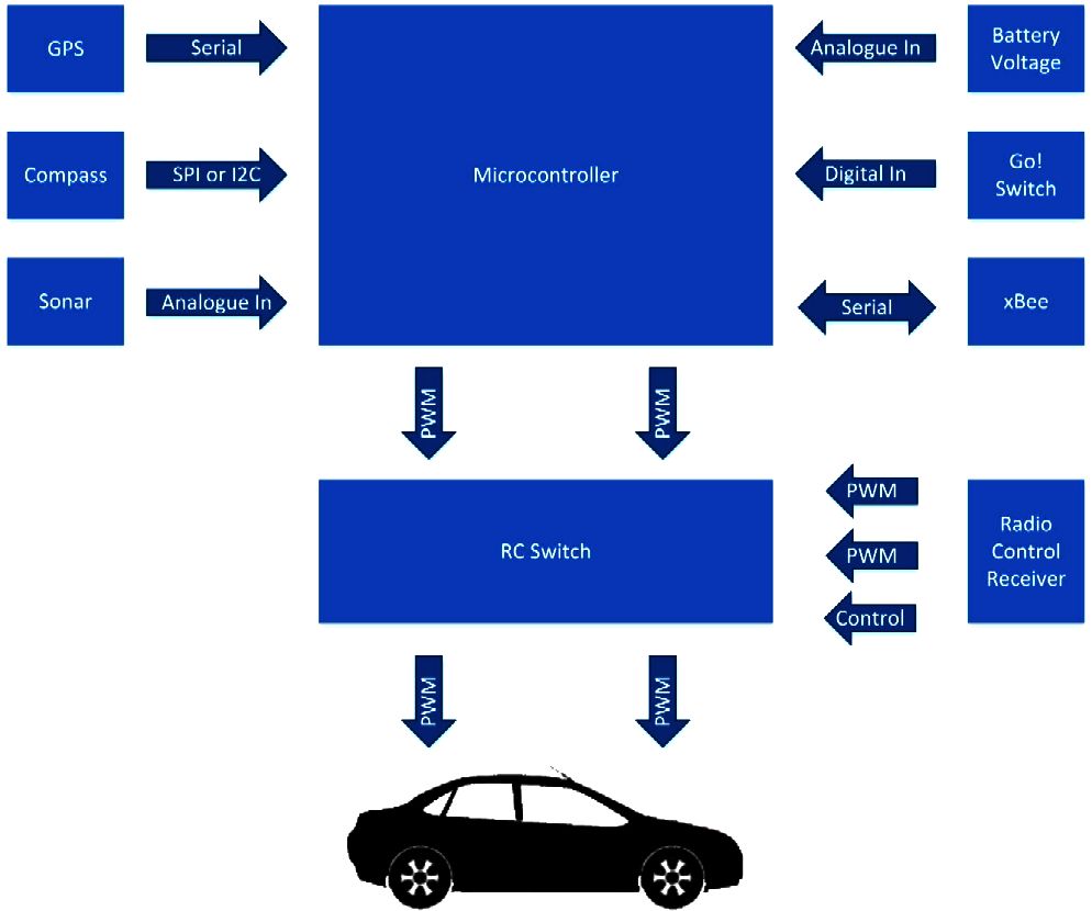
Autonomous vehicle system block diagram [1]. Circuit Diagram
* * The code will read the sensors and is set up to control the speed and direction of the robot's two motors * using an H-bridge integrated circuit (the L293D, included in your Bluebot kit). However, *you* must write * an algorithm that determines what the robot will do based on the sensor readings.